About a wood lathe. Construction of a homemade wood lathe
There was a period in the history of Russia when doing something with your own hands was a fashionable occupation. In the houses-museums of many famous personalities, you can find furniture and other household items made by the owners in their free time from literary and state activities. As you know, Peter I was a great lover of tinkering, who mastered many crafts during his life (carpentry, weapons, soldering, watchmaking, printing). The Russian tsar was famous for his ability to grind wooden parts on a lathe. Under the leadership of Peter, Russia was rapidly creating a navy, and the ships of those times had an abundance of chiseled parts, so probably Peter I could not master this craft.
Unfortunately, nowadays standard angular furniture has replaced elegant chiseled products, leaving the latter a place in museums and collectors' apartments. However, the chiseled elements of the platbands, cornices and stairs of wooden and stone houses built by our grandfathers and great-grandfathers are still pleasing to the eye. And the process of manufacturing chiseled parts causes a unique range of feelings when you observe how the contours of elegant bodies of rotation begin to appear against the background of a rough workpiece, the shape of which depends on the slightest movements of the cutter in the hand of the master, and the thin chips coming out from under the cutter spreads a subtle aroma of wood (although a lot of dust is also formed).
Here, to feel all these charms of turning, as well as to get the right parts, you will need a wood lathe. Of course, unlike the era of Peter I, it will not be the master's foot that will set the part in motion, but an electric motor. All other elements of the machine remained basically unchanged. So, let's consider the device of the simplest machine for wood (Fig. 1).
Wood lathe
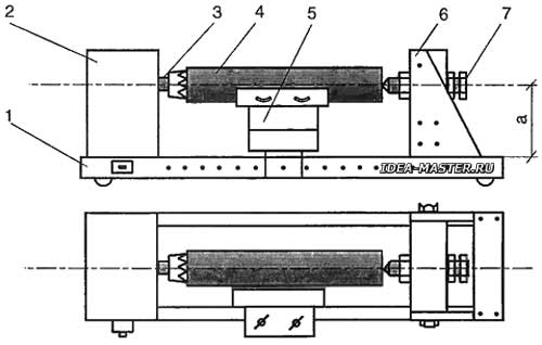 Fig. 1. Wood lathe construction: 1 — frame; 2 — drive; 3 — driving center; 4 — workpiece; 5 — stop for the cutter; 6 — tailstock; 7 — driven center (center-bolt); a — the height of the location of the driving center. |
Its main parts are a drive with a leading center, as well as a driven center mounted on the tailstock. The purpose of the driving center is to transfer the rotation from the motor shaft to the workpiece.
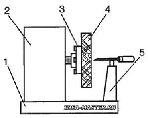 Fig. 2. The machine is only with a leading center («frontal»): 1 — frame; 2 — drive; 3 — faceplate; 4 — blank; 5 — stop for the cutter. |
The driven center, pressing the workpiece against the driving center, holds it in the working position. The drive consists of an electric motor and a rotation transmission mechanism (belt, clutch, gearbox), however, it is possible to manufacture the machine without additional rotation transmission mechanisms from the motor to the workpiece. So, the tasks of the leading center are: to transfer rotation from the drive to the workpiece, centering the workpiece and fixing it in this position until the end of processing. For «frontal» machines, that is, with one leading center, the latter provides both centering and fastening of the workpiece using a three- or four-cam chuck or faceplate (Fig. 2).
The purpose of the center with the tailstock is to center the workpiece and clamp it in the axial direction. It is clear that the leading center and the center of the tailstock should be located on the same centerline.
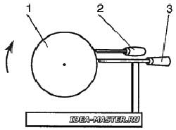 Fig. 3. Types of turning: 1 — blank; 2 — cutter for tangential cutting; 3 — cutter for radial cutting. |
Rigid fastening of both centers is provided by the frame (bed) of the machine (see Fig. 1). It, in addition to rigid fixation of the centers, allows you to move the tailstock in the axial direction. On the frame, an emphasis (podruchnik) for the cutter is also installed. It is necessary that the stop is easy to move both parallel and perpendicular to the axis of the machine and securely fix it in the right place. The height of the helper is made so that the cutter when cutting is located in a horizontal plane passing through the axis between the centers, although it is possible to position the cutter above this axis. In this case, tangential turning will be carried out (Fig. 3).
Note that the force to hold the cutter in the second case is slightly greater than in the first. I will immediately make a reservation that the above is the result of the experience I have accumulated in my home workshop, therefore deviations from the generally accepted provisions of theory and practice are possible. At this time, I have made four models of machines (for different purposes), three of them turned out to be successful, and one, alas, did not meet expectations. Based on the results of this activity, some conclusions have been drawn. I think they will be useful to those who decide to make a machine for turning wood. The main motive of my further presentation will be the topic: «Making a wood lathe with your own hands with a minimum set of tools and with minimal material consumption».
Developing the design of the machine, it is necessary to determine the minimum and maximum dimensions of future products. If these are chiseled parts for various auto or aircraft models, then it is desirable to have a machine of one size, if the elements of the interior and furniture are different. The dimensions of the part are also decisive for the choice of drive power and machine design. The shape of the parts also matters. For example, for turning parts whose diameter exceeds the length of the workpiece (plate), it is better to have a machine only with a leading center, on the spindle of which a cartridge or faceplate is installed (see fig. 2).
Now let's take a closer look at the design of the machine. The electric motor of the drive is designed to rotate the part, and the motor must provide sufficient force on the shaft to cut wood fibers. In industrial machines, speed boxes are provided, with the help of which different rotational speeds of the workpieces are set. In a homemade simple machine, you can adjust the spindle speed by using pulleys of different diameters in the transmission. However, this significantly complicates the design of the machine and increases the cost of materials and funds. By the way, the presence of several speeds at the machine is actually not necessary, because after spending a little more time on processing the part, it is usually possible to get the quality of the surface to be processed almost the same as when turning on a multi-speed machine. Having decided not to complicate my life with pulleys and belts, I simply installed the driving center on the motor shaft, that is, the motor shaft became the support shaft (spindle) of the machine. I will tell you about the installation of the drive center or faceplate on the motor shaft, as well as about some modification of the engine below. In the meantime, let's talk about the types of electric motors that are suitable for a lathe.
About electric motors for wood lathe
Collector AC motors for the machine are not entirely desirable, since without a load on the shaft at the rated supply voltage, they go into «separation» (uncontrolled increase in rotational speed). The fact is that with a weak impact of the cutter on the workpiece or even in the absence of such an impact (when removing thin chips, for example) the workpiece is gaining such great momentum that it can be torn out of the centers of the machine by centrifugal forces, which, of course, is very dangerous for the worker. Therefore, collector motors can be installed on lathe only with a gearbox or with an electronic speed controller. A variant of a lathe with a gearbox is a machine based on a household electric drill. An engine with an electronic speed controller is suitable, however, the «behavior» of the workpiece during turning does not allow in this case to obtain high-quality processing results. For a small turning machine modeler (the part size is larger than a match and smaller than a standard pencil), a DC collector motor is quite suitable. It can be a micro-electric motor from a tape recorder or from children's toys. Only here you will have to add another power supply to the drive, which provides the voltage necessary for the electric motor.
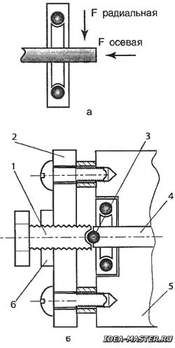 Fig. 4. Design of the additional thrust bearing: a — forces acting on the motor shaft; b — thrust bearing; 1 — thrust screw; 2 — steel plate; 3 — thrust bearing ball; 4 — motor shaft; 5 — motor housing; 6 — lock nut. |
For a wood lathe working with workpieces with a diameter of about 100 mm and a length of 700...800 mm, it is better to choose an asynchronous AC motor with a power from 250 to 1000 watts. The power characteristics of such engines allow them to provide a stable shaft rotation speed in a certain range of loads, and do not allow an increase in the rotational speed above the passport in the absence of a load. And the acoustic noise of asynchronous motors is less than that of collector motors. Some of their disadvantages (low starting torque, reduction of rotation speed under heavy load) for a simple lathe are not only not noticeable, but to some extent even useful. As you know, most asynchronous AC motors usually have a shaft rotation speed of 1800 to 3000 revolutions per minute (specific figures depend on the type of engine), but there cannot be more than 3000 revolutions per minute for design reasons. It seems to me that such characteristics of asynchronous motors allow them to be used for lathes without complex gears, and the motor shaft is capable of performing the duties of the machine spindle. However, we will have to work a little on the asynchronous motor designed for the machine. The fact is that the bearings installed in the electric motor are mainly designed for radial loads, that is, acting on the motor shaft at right angles (Fig. 4, a). In a lathe, a force directed along the shaft axis also acts on the shaft (this force occurs when the workpiece is attached between the leading and rear centers). Under the influence of such a force, the wear of bearings goes faster. There are two ways to solve this problem: to have a couple of new similar bearings in stock, or to modify the engine a little by installing an additional support on it that would compensate for the force acting on the shaft axis. For this purpose, a support bearing (bearing plate) is installed on the motor housing for the shaft, which consists of a steel ball suitable for the diameter of the process hole, usually already available at the end of the shaft, a steel plate and a preload screw with a lock nut (Fig. 4, b). The types of electric motors are different, so I do not give the dimensions of the bearing plate, but I will confine myself to the main idea. I repeat, most often there is already a technological hole in the end of the shaft, so it remains only to pick up a ball for it. The depth of the hole should be such that the ball enters it by 1/3 of its diameter. A similar hole is made in the end of the preload screw. A bearing support is fixed on the engine housing — a plate made of steel with a thickness of 3...5 mm. The plate has a threaded hole for the preload screw. The alignment of the holes in the plate and the shaft end is carried out as accurately as possible. With a screw, the ball is pressed with some force to the hole in the shaft, and with the help of a lock nut, the screw is fixed in the desired position. There are other options for mounting the preload screw, which depend on the type of electric motor. The only condition is the rigidity of the thrust bearing structure. If there is no rigidity, there will be no benefit from this bearing.
About the leading center of a wood lathe
The shape and method of manufacturing of the leading center is a matter of taste and capabilities of the master, so we will limit ourselves to considering only three of its types.
The center is made of thin-walled steel tube (Fig. 5, a). A steel tube is selected for it, which is put on the shaft of the electric motor with some effort. Prior to this, «teeth» in the shape of a triangle are formed at one end of the tube using a metal saw and a file. The advantage of this center is only one — ease of manufacture, but there are several disadvantages: the impossibility of quick disassembly (although when installing the tube on the shaft with a thread, this issue is removed); the impossibility of installing a workpiece whose diameter is less than the inner diameter of the tube; the operation of the machine in this case is possible only with two centers.
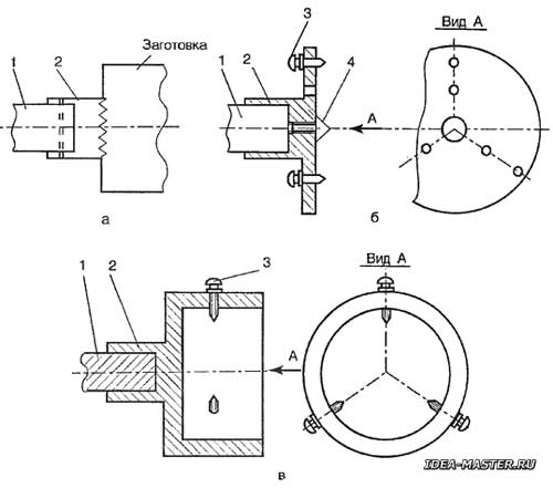 Fig. 5. Types of leading centers: a — from the tube; b — faceplate; c — cartridge; 1 — motor shaft; 2 — driving center; 3 — screws with pointed ends; 4 — central screw. |
The center is the faceplate (Fig. 5, b). Screws with M4 or M5 thread sharpened on a cone are inserted into the radially located holes of the faceplate and they are fastened with nuts. It is clear that the tips of the screws perform the duties of the teeth of the center of the tube. When working with one central screw, screws are passed through the remaining holes in the faceplate, with which the workpiece is attached to the faceplate. In the central hole of the faceplate, an additional center is often installed from a tube for small diameter parts. The main disadvantage of the faceplate is that when processing parts with a diameter smaller than that of the faceplate, it is necessary to install a protective casing over the faceplate.
The center is the simplest cartridge (fig. 5, c). The design of the center is clear from the drawing. The main disadvantages: the complexity of the cartridge manufacturing and the need to process the end of the workpiece for the inner diameter of the cartridge.
It is desirable that all types of centers are replaceable, provide sufficient rigidity of the workpiece attachment and do not have sharp protruding parts.
About wood lathe frame
The option of mounting the electric motor on the frame depends on the design of the engine. And when installing the electric motor on the frame, the following circumstances have to be taken into account: the motor shaft is oriented parallel to the lateral (long) faces of the machine frame; the height of the shaft position above the frame (see Fig. 1), as well as the distance from the stop for the cutter to the workpiece determine the maximum diameter of the workpiece; the motor mounting on the frame should be rigid, but at the same time allow a slight adjustment of the position of the motor; for processing short parts of large diameter, it is necessary to provide for fixing the stop for the cutter across the frame (see Fig. 2), organizing the so-called «frontal» turning; for an engine with an open design, it is necessary to make a casing made of thin tin; a lock should be provided on the motor shaft (a through hole for the rod or a turn-key groove), which would allow holding the shaft when changing centers; the power switch is installed in an accessible but safe area of the machine, so that the hand, when turning on (off) the machine, does not fall into the rotation zone of the center and the workpiece.
About the rear (driven) center of the lathe
To mount a long blank in the machine, it is necessary to have, in addition to the leading center, a clamping fixed (less often rotating) center, which is located on the tailstock of the machine (see Fig. 1). The tailstock is a rigid structure that can be moved along the frame. Usually the fixed center is made of a bolt, the threaded end of which is sharpened in the form of a cone. Accordingly, the tailstock has an internal thread for the bolt. Thus, by rotating the bolt center in the tailstock, it is possible to clamp the workpiece between both centers.
Of course, the center bolt must be on the same axis with the leading center. Taking into account the fact that the tailstock can be moved to the leading center or moved away from it, 20-30-millimeter stroke of the center bolt is enough to clamp a workpiece of one or another length between the centers. The diameter and thread of the center screw are determined by the size of the workpiece, but even for workpieces with a diameter of 100 mm, it is enough to have a screw with a diameter of 10...12 mm. As already mentioned, the end of the screw is processed into a cone, and then ground. Preloading the workpiece, it is desirable to lubricate the screw cone with any engine oil.
Of the main parts of the lathe, we did not tell only about the stop (podruchnik) for the cutter. We'll do it a little later. In the meantime, let's try to turn the above theory into a real machine. (For the transformation of theory into reality, see Electric drill-based lathe and Homemade lathe with electric motor).
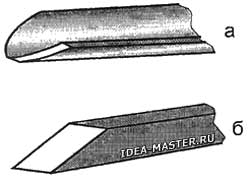 Fig. 6. Incisors: a — semicircular; b — flat. |
A little bit about cutters and turning techniques
For wood processing, through semicircular incisors are usually used (Fig. 6, a), and flat undercut incisors (Fig. 6, b). The dimensions of the incisors depend on the dimensions of the parts obtained. In addition to these two cutters, special cutters (cut-off, shaped) are also used when working on a lathe. Cutters are usually made from chisels and files. A sharpened blade from a hacksaw is suitable as a pruning cutter.
Preparation of wood for turning
The blanks should be dry, although it is better to sharpen the wood of apple trees and similar hardwoods wet, and then dry the finished product. When processing sparsely layered wood, chips are possible, which hopelessly spoil the detail.
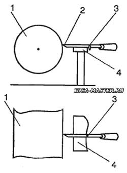 Fig. 7. «Copier»: 1 — blank; 2 — cutter; 3 — stop; 4 — template-copier. |
Before turning, the workpieces must be given a shape close to cylindrical. They do this with an axe or a plane. Then the centers are outlined at the ends of the workpiece and set it on the machine. (I, pressing the workpiece with the center bolt, put a small washer or nut under the latter, which protects the workpiece from splitting. — Editor's note). To obtain several identical parts, the whole process must be divided into stages, make a set of templates from cardboard or tinplate and use them to control the size and shape of the workpieces being processed at each stage. In the case of large batches of parts, the work will be accelerated by the use of a simple copying device (Fig. 7). In this case, the cutter is supplemented with an emphasis in the form of a metal short rod. Moreover, the smaller the diameter of the rod, the more accurately the device works. It is clear that the emphasis, resting on the template mounted on the helper, restricts the movement of the cutter, which follows the bends of the template, transferring its shape to the workpiece. The template is usually made of 3 mm plywood. To obtain overhead chiseled parts (for example, when finishing window frames), you can cut the finished part in half along the axial plane, or you can prepare a billet of two halves. To do this, you will have to firmly fasten the halves together with screws and carve a round part out of them. After the turning is completed, the screws are unscrewed and two identical pads are obtained. All the other tricks and highlights will come to the turner after the first turning experiments.
All materials of the section «Ideas for the master»
| Share this page on social networks: |
