Homemade wood lathe with electric motor. A lathe with your own hands
I want to offer readers a more convenient construction of a homemade lathe with an electric motor (Fig. 1 and 2) (for a less convenient machine design, see Electric drill-based lathe).
Homemade wood lathe
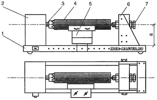
 Fig. 1. Wood lathe construction: 1 — frame; 2 — drive; 3 — driving center; 4 — workpiece; 5 — stop for the cutter; 6 — tailstock; 7 — driven center (center-bolt); a — the height of the location of the driving center. |
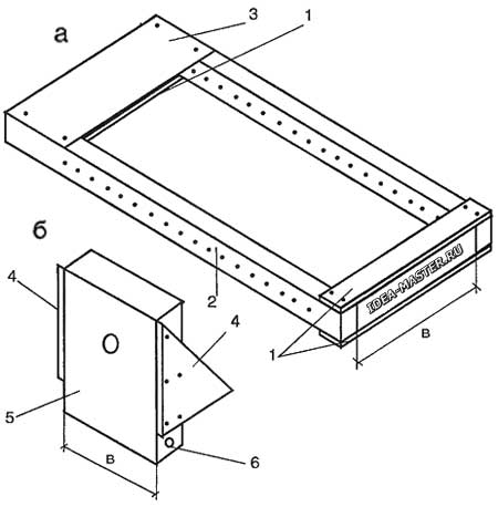
The machine frame here is made of two rails (1000x50x30 mm). I note that the dimensions in the text are all approximate. Slats should have right angles, and their faces are treated with a jointer. Connect the slats with each other using plywood linings (5 mm thick or more) or aluminum (see Fig. 2). A metal plate is better suited for the upper lining on the engine side. I will not dwell specifically on the ways of mounting the engine on the frame, since different engines have different housings.
 Fig. 2. Frame (a) and tailstock (b) of the lathe: 1 — plywood linings; 2 — rail with holes; 3 — metal lining; 4 — stop made of 10 mm plywood; 5 — tailstock housing; 6 — nut hole with external thread. |
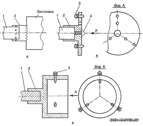
Before connecting the rails into the frame, we drill a number of holes in the rails with a step of 50 mm. The diameter of each hole is 6.2...6.5 mm. These holes will be needed for mounting on the tailstock frame. The pitch of the holes in 50 mm is chosen based on the calculation that the lengths of the machined parts will differ by 50 mm. For example, if the minimum length of the workpiece is 50 mm, then the next one will be 100 mm long and so on. A similar option is chosen to simplify the design of the tailstock. Smooth movement of the headstock on the frame would lead to a complication of the machine. We put the engine on the assembled frame. According to the dimensions of the engine shaft, we do (select, order) one or another leading center (the types of centers are shown in Fig. 3).
 Fig. 3. Types of leading centers: a — from the tube; b — faceplate; c — cartridge; 1 — motor shaft; 2 — driving center; 3 — screws with pointed ends; 4 — central screw. |
After that, we proceed to the manufacture of the tailstock. The principle of operation of the center bolt here is the same as in the version of the machine with an electric drill (see Electric drill-based lathe). The difference is in the way the headstock is attached to the frame. The tailstock is made of a bar of wood (Fig. 2, b). From plywood (8...10 mm thick), we cut out the side stops and attach them to the bar with glue and screws. The resulting blank of the headstock is installed on the frame (between the rails) and, pressing it against the motor shaft or the driving center, mark the center of the future hole for the center bolt on the headstock. For accurate marking, a ball can be installed in the technological hole of the shaft, which, when the headstock is pushed onto the engine shaft, will give a clear imprint of the center. We install the center bolt into the tailstock in the same way as in the version of the machine with a drill, or for reliability we press a nut or a tube with a thread corresponding to the screw into the bar. To fix the tailstock on the frame, we screw metal nuts into the headstock body with glue (plastic ones are undesirable) from the corner furniture screed (the whole set of screed consists of a corner, two screws and two nuts with additional necessary thread). Marking the holes for the nuts is done by installing the tailstock on the frame, marking through the holes in the frame rails. Next, according to the marking on both sides of the headstock, we drill a hole with a diameter of 10...11 mm and screw the nuts into them. Also, two M6 screws will be needed to mount the headstock, having a turnkey head or in the form of a lamb. The length of the screws depends on the thickness of the frame rails.
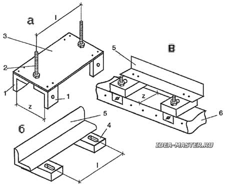
The most difficult element of this homemade lathe is the emphasis under the cutter (podruchnik). If it is assumed that the length of the workpiece will be small (about 300 mm), then an emphasis of the type a lathe with a drill, but with large sizes of workpieces to be processed, you will have to make another stop, the design of which is shown in Fig. 4.
 Fig. 4. Design of the stop for the cutter: a — lower part; b — upper part; c — stop on the frame rail; 1 — steel corners; 2 — screws; 3 — steel plate; 4 — wooden bar with a slot; 5 — aluminum corner (the actual stop); 6 — frame rail. |
Since it is not so easy to pick up a metal profile (channel), which would be put on the frame rail without much backlash, then we make the profile from two corners. I note that it is better to take steel corners, because they will have to be threaded. For the very same stop, an aluminum corner is also suitable. The wooden parts of the podruchnik (short slats with slits) are made from dense wood (birch, maple). To attach the stop to the frame, use the same holes as for installing the tailstock. In conclusion, I want to repeat that when describing the manufacturing technology of machine tools, only the main points of construction are outlined, more specific devices, for example, copiers are a matter of taste for every master.
All materials of the section «Ideas for the master»
| Share this page on social networks: |
