
Homemade wind turbine for heating a country house
Our title is not a joke or a typo. The wind can really warm the dwelling. However, to do this, you will have to assemble a wind turbine, about which our story will go.

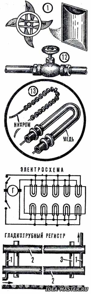
Take a look at the diagram. The electric energy generated by the rotating windmill from the generator goes directly to the electric heaters, resembling the well-known boilers. They are built into the housing of a thermal accumulator — a large insulated tank filled with water. The water is heated continuously while the generator is running: the stronger the wind, the greater the current and, accordingly, the more thermal energy. This is briefly the principle of the system.
Wind turbine for home heating

1 — rotor; 2 — short extensions; 3 — bearing assembly; 4 — rotor axis; 5 — step-up gearbox; 6 — long stretches; 7 — tower; 8 — generator; 9 — expansion tank; 10 — batteries; 11 — return line; 12 — control valves; 13 — heaters; 14 — capacity of the heat accumulator.
 Our homemade heat accumulator is connected to a conventional water heating system at home. Since the battery capacity is large, the heat supply to the batteries will be stable. And so that the battery does not have unnecessary energy losses, it is packed, as if in a fur coat, in a heat-insulating material. Regulating valves are used to regulate and redistribute the heat flow. People have gone to work — you can cover the taps a little so that more heat has accumulated in the battery by their arrival.
Water moves through the pipes by gravity: after all, warm water has a lower density than cold water, and therefore it rises up. And the denser cold water goes down, gets through the lower pipe into the battery, and everything starts over. Although, of course, there is no «beginning» or «end» here, but there is only a constant convection movement of the coolant. So, the theoretical picture is clear. It remains to build the installation?.. Take your time, first you need to calculate the required generator power. It should be more powerful the more heat loss of the house that we are going to heat.
These heat losses are calculated by the formula: Q = VqO(t bh — t ar)n, where V is the volume of the building (m³), t bh is the minimum allowable indoor air temperature equal to 18 °C, t nar is the minimum outdoor air temperature for this area; qo is the volumetric heat capacity of the building, for single-storey houses assumed to be equal to 0.81 W/ m³ x deg.; n is a dimensionless correction factor for climatic conditions, assumed to be equal to: at: at t nar greater than or equal to — 10 °C.....1,2; t nar greater than or equal to — 20 °C.....1,1; t nar greater than or equal to — 30 °C.....1,0; t nar is greater than or equal to - 40 °C....0.9.
For example, in the Odessa region, the average temperature of the coldest five-day period is -15 °C. For the Kiev region it is already -21 °C, and for the Leningrad region -25 °C. Which of these areas should I take as an example? Let's take the "average": Kiev. If the area of a well-insulated winter house is 46 m ² with a ceiling height of 2.5 m, then with a volume of 46x2.5 = 115 m ³ heat loss per unit of time for the Kiev region will be: Q = 115x0.81x[18—(-21)]x1.1 = 4000 watts. Therefore, for heating the house in the coldest period, taking into account the reserve coefficient (1.15...1.17), we need to have a heating capacity heating systems approximately 4700 watts. This should be the minimum generator power for the Kiev region. It seems that it will not be difficult for you to make a similar calculation based on the climatic data of the area where you live.
In the convection heating system, it is best to use cast-iron radiators, for example, M-140AO. They are sold in building materials stores. Such radiators make it possible to use large diameter pipes, which is very important for good water circulation. In addition, due to their large mass, they accumulate well and retain heat for a long time, they are durable compared to steel ones.
Let be the total length of the outer walls of the largest room (see Fig.) it is approximately 30% of the total length of the exterior walls of the house. Then the heat loss of this room will be 4700x0.3 = 1410 watts. Based on the fact that each square meter of the battery surface has a heat loss of about 500 watts, we calculate the number of sections in the largest room, provided that the surface of each section is 0.3 m : 1410 : (500x0.3) = approximately 10 sections. For all rooms of the house, the total number of sections will be approximately 32 sections. These batteries should be distributed throughout the premises so that there are more sections in the living rooms than in other places.
The generator whose power we have determined is AC or DC with any operating voltage. Some types of electric motors can be used as generators, for example, any DC motor. If the operating speed of the generator, at which it produces current, is greater than the number of revolutions of our wind rotor (depending on the strength of the wind, it can be 150-500 rpm), you need to use a step-up gearbox. A gearbox from an outboard outboard motor with a power of at least 5 hp will do. The use of a step-up gearbox, in addition, will make it possible to position the generator horizontally: after all, the boat gearbox transmits force at an angle of 90 °.
Heaters are ready-made spirals from electric irons and electric fireplaces, available for sale. If the power of one heater is small, you need to make several identical heaters, which in total will correspond to the maximum power of the generator. The heaters are connected to the generator in parallel, and several heaters are mounted in reserve. Each spiral is inserted into a U-shaped copper tube with an inner diameter of 12-16 mm, depending on the size of the spiral. The tube is soldered to the container body with ordinary tin solder. To do this, it is convenient to use a gasoline burner. In this case, a mechanical fastening with a seal can also be used. Spirals with insulators are dragged through a copper tube so that the leads from the spirals begin inside the container at a distance of 5-6 cm from its wall. The terminals of the heaters should be isolated and output to the switch. Thus, when repairing parts of the heaters, the rest continue to work.
The heat accumulator for our design option is a welded steel bath made of 3-5 mm thick sheet with a capacity of 5000 liters, placed in a wooden box mounted on a solid platform. You can use a smaller capacity, but then the amount of heat stored by it will be less. Slag wool is used as a heat insulator. From the outside, the box is closed with two layers of parchment or roofing material and covered from the sides and top with expanded clay, or sawdust in half with slag, or dry sand. Such a thermal accumulator provides heating of the premises for 3-4 days if the generator is turned off for some reason.
The role of a thermal accumulator in an extreme case can be played by a container made of reinforced concrete. In this case, special attention should be paid to the support: it should be especially rigid and durable so that the container does not crack. The room (sub-floor) for the tank should be dry throughout the year, including during the spring increase in the groundwater level.
The rotor is a drum with a height of 1.5 m and a diameter of 3.6 m. The blades are made of standard sheets of galvanized roofing steel with a size of 1.5x2.5 m. The blade frame and other stiffeners are made of steel or aluminum corners. The rigidity of the rotor structure is given by the upper and lower rings, crosspieces (also made of corners), cables with adjusting elements.
The rotor axis is a piece of pipe with an outer diameter of 60-80 mm. Bearings are selected in advance, since their dimensions must be consistent with the dimensions of the axis. When installing the rotor, the crosspieces are first welded, and then the blades are bolted to them. All structural elements should be positioned symmetrically relative to the center lines, since the balancing of the structure depends on this.
The mast is welded from a corner with a side of 60-80 mm. For its greater stability, steel cable extensions are used. Adjustment elements on the tripwires are mandatory.
Installation of the rotor and other equipment is carried out on the ground. It is possible to raise the masts, as well as lower them, only in calm weather. Of course, do not forget to paint the rotor and the mast with meerkat, and then with oil paint.
All materials of the section «Ideas for the master»
| Share this page on social networks: |